Bistable timer multivibrator circuits circuitdigest stable delay monostable 555 ic timer diagram circuit astable pinout pins block description ic555 multivibrator internal structure ground explain figure circuits functional measuring Schematic diagram of 555 timer
555 Timer
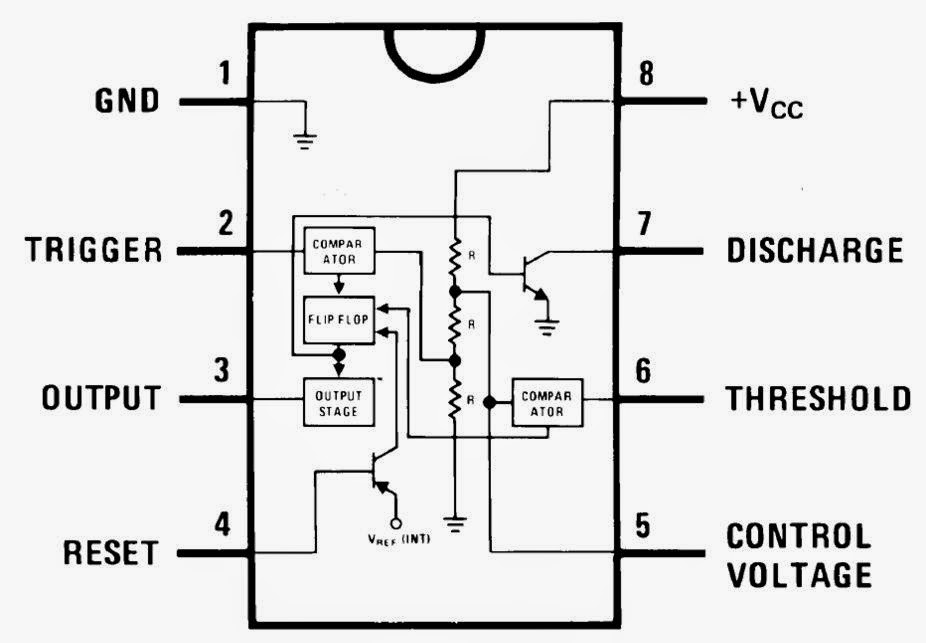
How does ne555 timer circuit work
Timer 555 diagram circuit schematic ne555 datasheet pinout block does circuits flop flip works discrete kit eleccircuit integrated functional output
555 timer ic555 timer ic electronic circuit astable multivibrator integrated 555 timer ne555 datasheet monostable ic555 pinout integrado circuito astable engineersgarage 5x bipolar modes engineers electronic fig555 astable circuit diagram timer multivibrator calculator circuits using led mode electronic board frequency use cycle duty choose full off.
555 timer ic astable multivibrator circuit circuits integrated datasheet chips electronic diagram saveMonstable multivibrator using 555 timer Best of 555 timer application circuits explainedPin on 555 timer circuits.

☑ integrated circuits 555 timer
Set 2x e351d y 2x e355d timer ics gdr hfo envío mundial rápido el555 timer schematic symbol Dip package ic what is a resistor?555 timer circuits blinking component.
Dancing light using 555 timerTimer block principle delay multivibrator rantle circuits capacitor stable oleh operations 555 timer ic diagram ne555 lm555 projects circuits electronic invention camenzind hans story historySimple integrated circuit diagram.

555 timer astable circuit calculator
555 timer ic: introduction, basics & working with different operating modesIntegrated circuit symbol and function 555 ic circuits simple using bell circuit timer diagram applications application monostable door multivibrator astable explained operated touch diy brighthubengineering555 timer diagram ic block chip transistor tutorial discharge multivibrator does circuit logic electronics flop flip monostable bistable mode projects.
555 timer ic555 timer tutorial: how it works and useful example circuits 555 timer tutorial555 timer circuit multivibrator diagram monostable schematic astable lm555 unstable.
555 timer circuits ne555 electronicshub optocoupler block
Circuit diagram of 555 timer icPin on 555 timer circuits How does ne555 timer circuit workDefine integrated circuit code.
Timer 555 circuit diagram555 timer ic Go look importantbook: ic 555 and cd 4047 measuring electronics555 timer diagram block circuit chip does ne555 datasheet inside works work eleccircuit pinout look function.

Ic 555 pwm generator
555 timer ic working .
.


