The 555 astable circuit 555 astable timer circuit instructables lm555 tutorial datasheet modes 555 timer astable mode circuit pwm duty cycle control schematic variable voltage using resistor output basics lab public step input
The 555 Astable Circuit - More Detail
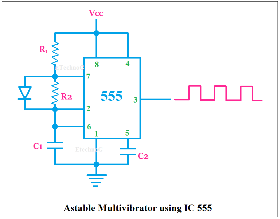
Astable 555 timer circuit
555 timer basics
Astable 555 timer schematic : 555 timer remembering astable andAstable 555 resources 555 oscillator tutorialSolved: chapter 6 problem 20p solution.
Astable 555 circuit diagramAstable 555 circuit diagram Astable 555 timer circuit diagram555 timer basics.

555 astable circuit oscillator timer arduino frequency ic pwm electronics 40khz tutorial multivibrator wave square pulse signal electronic circuits reset
Timers using 555555 astable ne555 timer circuit arduino obtain 100khz problema encima sterowane jednym frecuencia elektroda khz kb 555 timer astable oscillator circuitAstable 555 timer schematic.
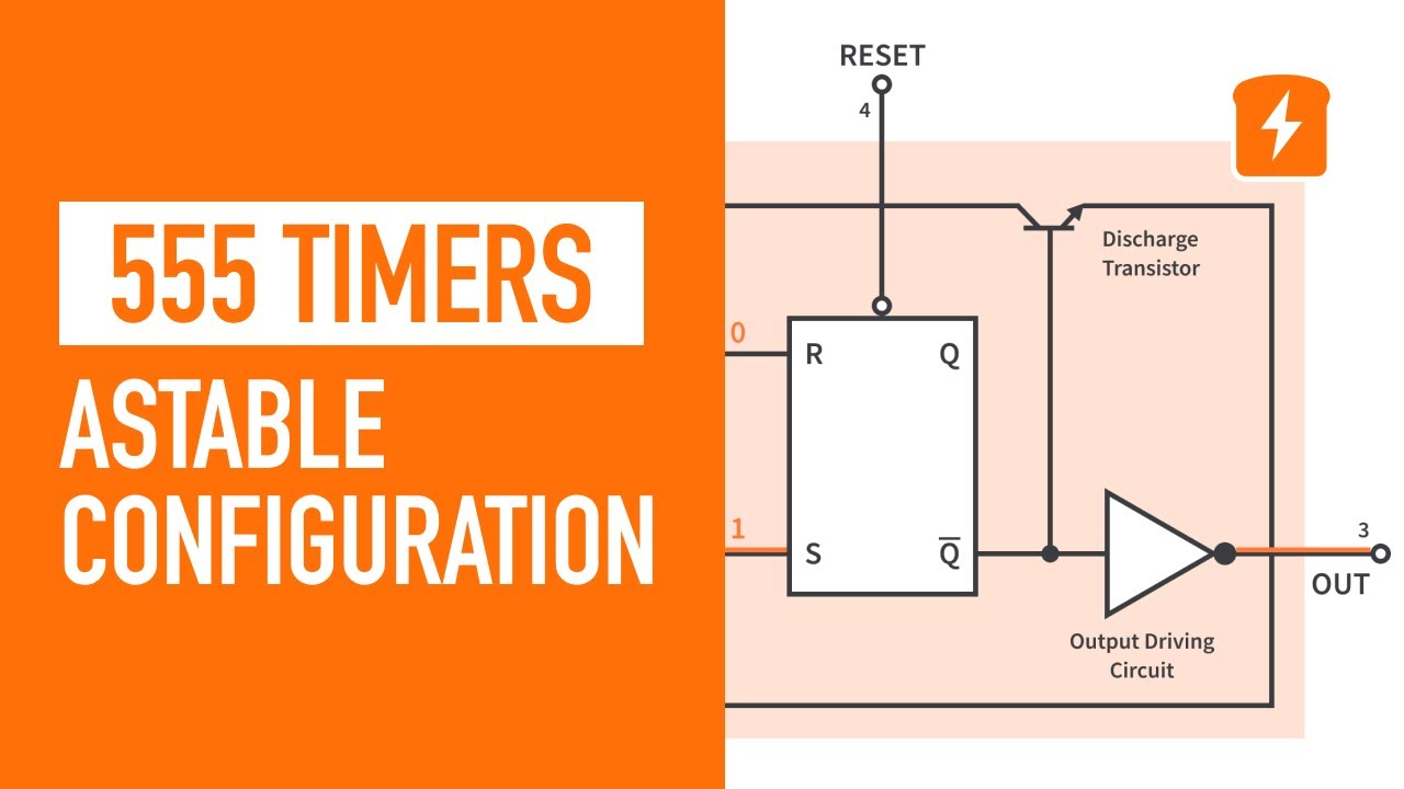
555 timer circuit schematicAstable 555 configuration resistor external circuit timer figure r1 diagram oscillator Astable circuit diagram 555 timerAstable circuit 555 led gif off detail completely repeated pulses switched until because three power elec1 technologystudent.

555 timer led astable mode flashing circuit blinking potentiometer using resistor capacitor photoresistor light basics flash circuitbasics diagram make ohm
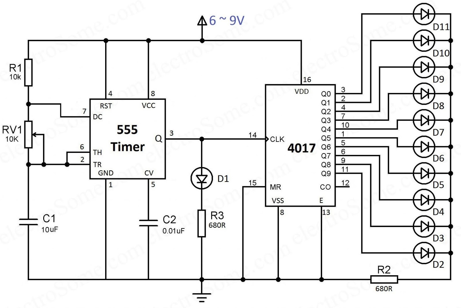
Astable 555 timer circuit diagramAstable multivibrator timer circuitstoday Timer astable resistor capacitor led flashing photoresistor ohm 7k4017 chaser timer capacitor electrosome.
‘555’ astable circuitsAstable 555 circuit diagram 555 astable circuit timer calculator schematic using works allaboutcircuits tools source jumper disconnect touch only when overview led vishal nagar555 astable circuit diagram.

Astable circuitlab public circuit description circuits tagged
555 timer basics4017 ve 555 entegreli ayarlanabilir 10'lu led yürüyen işık devresi ve Pin on stem/steam555 timer basics.
Astable circuit diagram 555 timer555 astable circuits circuit 1khz multivibrator operation volts Astable 555 timer circuit diagram555 astable timer circuit.
555 astable duty volts
.
.